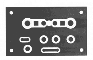
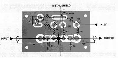
The transistor must be shielded from the input components and in constructing this circuit, the wirings must be as short as possible. For best results, the cable must be directly soldered to the PCB. The circuit should be installed near the antenna and housed in a water proofed case.
The power supply for this uhf tv antenna amplifier is fed through the cable by using a choke coil. To prevent the DC voltage from getting into the TV set, the coaxial cable must be coupled to the set through a small value capacitor.
To align the amplifier, just adjust P1 until the best reception is achieved. It means a collector current between 5 and 15 mA.
UHF antenna amplifier circuit diagram
 |
| LI, L2 = Aircore 2 turns 0.5mm ø3mm (coil diameter) L3, L4 = 10 uH HF choke or 0.2mm ø10 turns in ferrite core |
UHF tv antenna amplifier PCB layout

UHF antenna amplifier parts placement layout


No comments:
Post a Comment
saran dan coment teman teman sangat membantu pertumbuhan blog ini,terimakasih