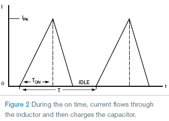
Almost all inexpensive commercial LED flashlights use a 4.5 V power supply—three AA or AAA batteries—because white LEDs require 3.3 to 3.5 V to fully turn on. Thus, there is a voltage gap between LEDs and traditional 3 V incandescent-flashlight bulbs. The voltage difference makes for a difficult—but not impossible—transition from the old flashlight to an LED flashlight. The simple circuit in Figure 1 solves this problem.
The circuit is just a typical voltage booster comprising six components that you can mount on a small PCB (printed-circuit board) measuring less than 1 in 2. Component selection and their values are, however, important. IC1, an Atmel ATtiny13 microcontroller, works as a charge pump for boost control. Its internal oscillator frequency is 1.2 MHz at 3.5 V, and it can operate with voltages as low as 1.8 V with low power consumption. The ATtiny13 has a small, eight-pin footprint.
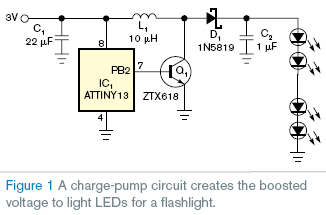
Q1 is a low-saturation-voltage ZTX618 NPN transistor that can handle more than 3 A of collector current. D1 is a Schottky diode with low forward-voltage drop to achieve high efficiency. When you apply the 3 V supply-voltage power to IC1, IC1 outputs a high pulse that turns on Q1. Its collector is effectively grounded. Inductor L1 charges linearly from 0A to some peak current until IC1 outputs a logic low, and Q1 then turns off (Figure 2). This circuit works only when the inductor is not saturated, so choosing the right inductor is important. At that moment, the established magnetic field in L1 collapses, causing a reverse induced voltage that makes D1 conduct. The energy in L1 transfers to C2, which stores the energy until it is sufficient to light up the LEDs. The relationship between the supply voltage (VIN), the inductor (L), its peak current (IPK), and the microcontroller’s on time (TON) is VIN=L×IPK/TON.
For a supply voltage of 3 V, you should select an inductor with a nominal value of 10 µH and a saturation current larger than 1.5 A. You can calculate the microcontroller’s on time as 5 µsec.
Listing 1 uses this value for the charge pump’s on time. The program in Listing 1 is so simple that it takes only 22 bytes of the 1-kbyte program memory. The charge-pump-control function is easy to understand. The instruction Sbi portb, 2 tells the microcontroller to output a logic high to turn on the charge pump. Because the microcontroller works at 1.2 MHz by its internal oscillator, each NOP (nonoperation) takes one clock cycle, or 0.83 µsec, to execute, so the on time is 5 µsec. Similarly, Cbi portb, 2 tells the microcontroller to output a logic low that turns off the charge pump.
Measurement shows that the circuit works at a 100-kHz switching frequency and that the actual output is 17 V / 35 mA for five LEDs and 32 V / 20 mA for 10 LEDs. Unlike the usual voltage-booster circuit, this circuit needs no resistor, which wastes energy and generates useless heat, as a voltage divider or a sensor.


No comments:
Post a Comment
saran dan coment teman teman sangat membantu pertumbuhan blog ini,terimakasih